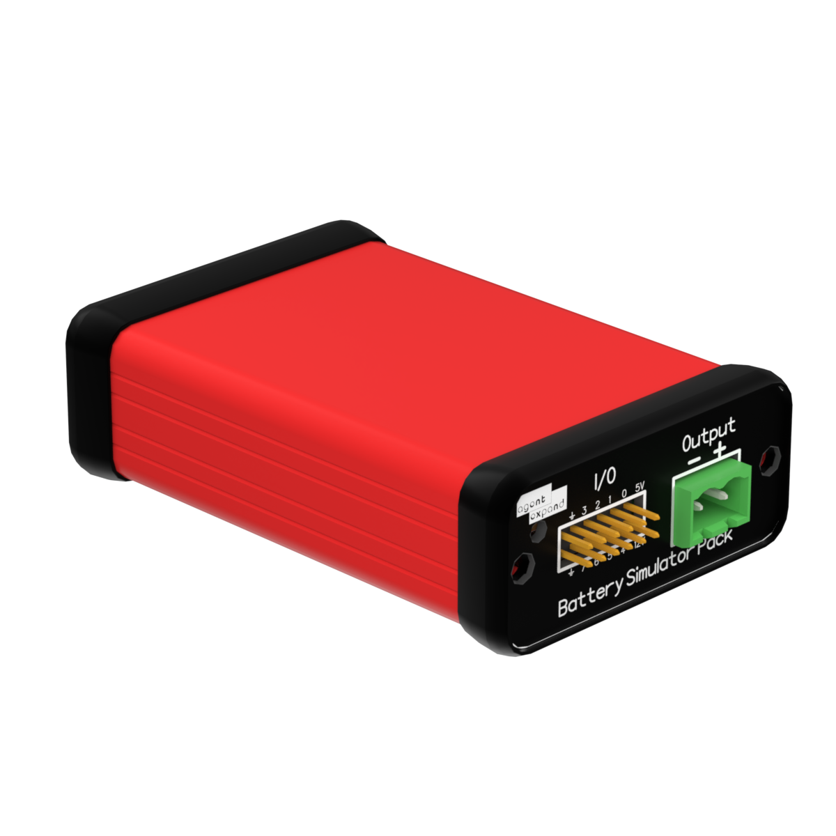
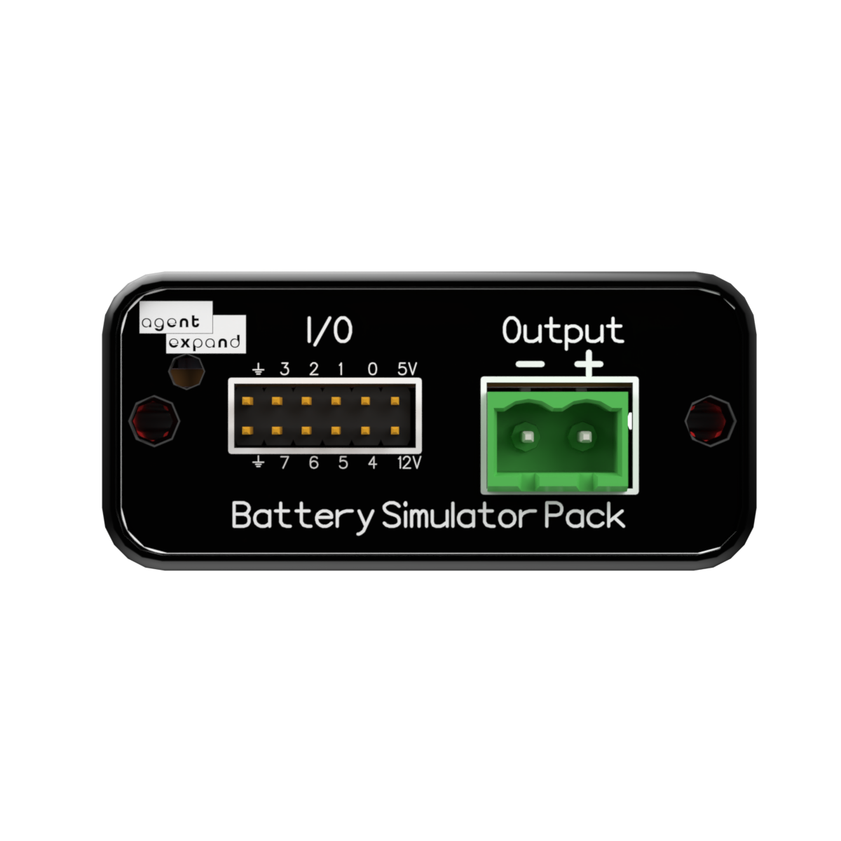
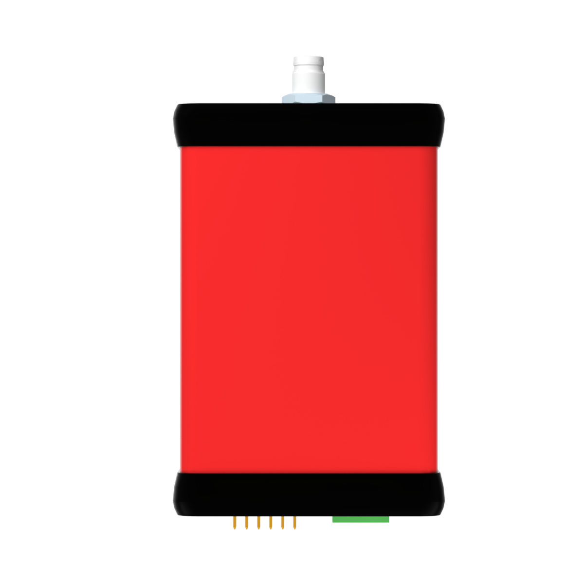
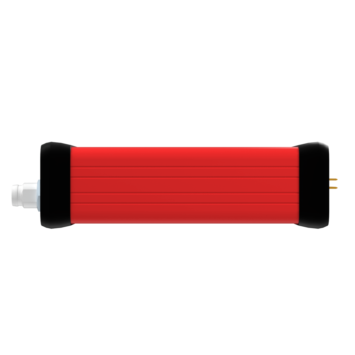
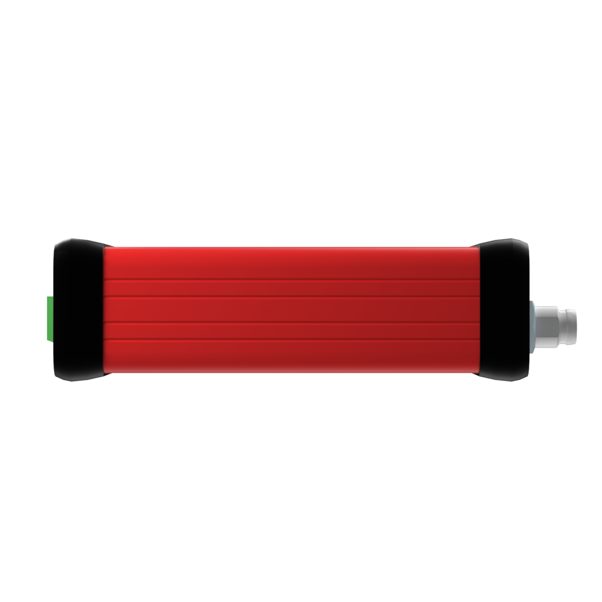
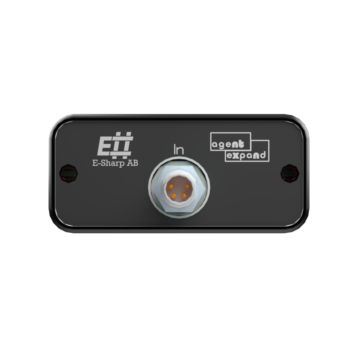
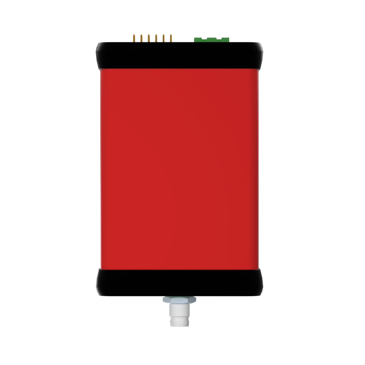
Battery Simulator
Test battery-powered devices without physical batteries — an isolated, programmable source/sink with measurement.
- Galvanically isolated output (isolated DC/DC + digital isolators)
- Output voltage 0–10 V, max 1 A, regulated voltage with constant-current limit
- Programmable source/sink (bidirectional)
- Controlled over I²C; 8 programmable DAC/ADC channels on the isolated side
- Over-current protection with automatic shutdown
ESH10000556 is a galvanically isolated, programmable power module that emulates battery behaviour in production and verification. It provides a controlled, isolated voltage and current output with built-in measurement and protection, so battery-powered devices can be tested safely and repeatably without physical batteries. The isolation barrier separates the supply domain from the DUT side — no extra isolation is needed towards the DUT.
Specifications, connections & manual
All technical material on the page — expand a section, or download the whole datasheet as a PDF.
Specifications
| Parameter | Value |
|---|---|
| Input interface | Expand Interface |
| Output voltage range | 0–10 V |
| Maximum output current | 1 A |
| Output mode | Regulated voltage with constant-current limit |
| Output type | Programmable sink / source (bidirectional) |
| Isolation | Galvanic (isolated DC/DC + digital isolators) |
| Control interface | I²C |
| DAC/ADC channels (isolated side) | 8 × programmable, 0–5 V |
| Overcurrent protection | Yes — detection and shutdown |
Manual
Hardware
Powered via the Expand Interface, which provides the input supply. Connect the DUT to the isolated output terminals; the galvanic barrier separates the input domain from the DUT-facing output.
Software
Controlled over I²C. Programmable: output voltage (0–10 V), current limit (up to 1 A; constant-current mode engages automatically at the limit), and output enable/disable. Eight programmable DAC/ADC channels on the isolated side are available for auxiliary signal control and measurement. Readback over I²C: output voltage, source current, sink current. Overcurrent events trigger automatic shutdown — the host clears the fault and re-enables the output.
Pinout
J1 — Output connector
| Pin | Signal | Description |
|---|---|---|
| 1 | VOUT+ | Isolated output voltage |
| 2 | GND | Isolated output ground |
J3 — Expand Interface (M8)
| Pin | Signal | Description |
|---|---|---|
| 1 | GND | Non-isolated ground |
| 2 | I2C-LR+ | I²C Long Range, differential (+) |
| 3 | VIN | Input voltage |
| 4 | I2C-LR− | I²C Long Range, differential (−) |
Note: the Expand Interface uses I²C Long Range (a differential I²C variant) and is not compatible with standard I²C (SDA/SCL).
Application notes, cases & news
Insights tagged for this product.
The right Accordion for your bench?
Tell us what you're testing and we'll find the right configuration — or say honestly if a standard setup is enough.