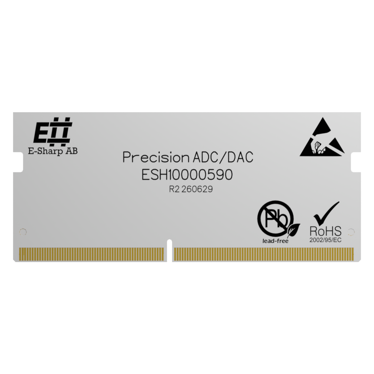
Precision ADC/DAC
High-resolution measurement and stimulus — 24-bit ADC and 16-bit DAC with per-channel calibration.
- 12 ADC inputs, 24-bit (ADS124S08); 8 DAC outputs, 16-bit (AD5675R)
- Per-channel gain/offset calibration, stored and applied automatically
- Analogue or pseudo-digital operation (configurable VL/VH thresholds)
- High-speed numeric acquisition (ADC) — min/max/mean/standard deviation
- ADC ±2.625 V bipolar or 0–AVDD; DAC 0–2.5 V (gain 1) or 0–5 V (gain 2)
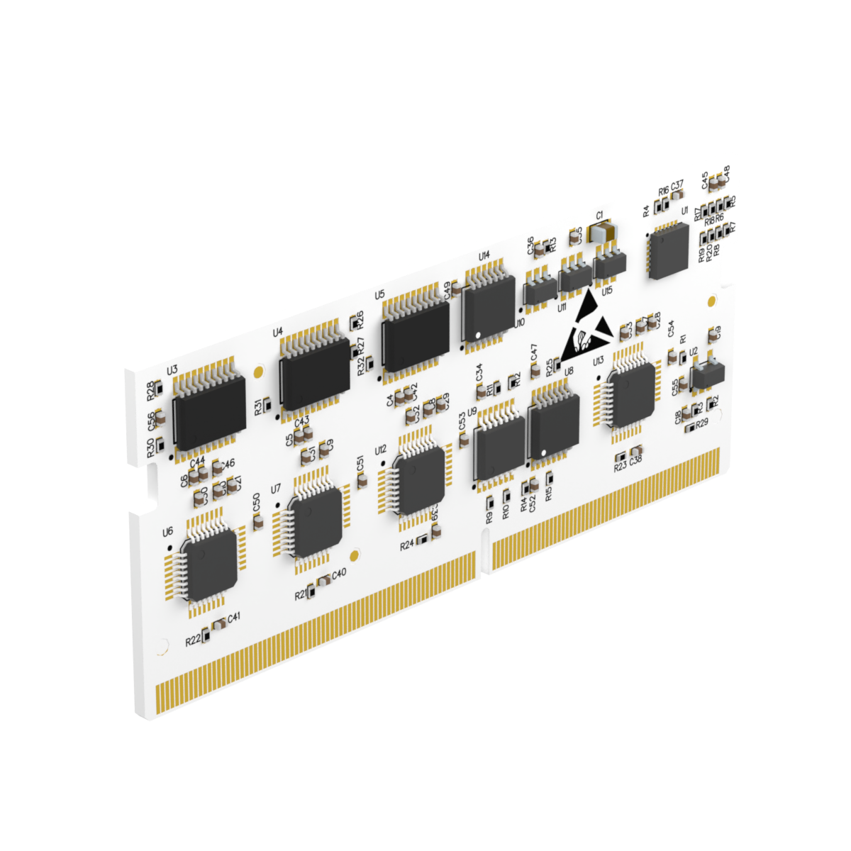
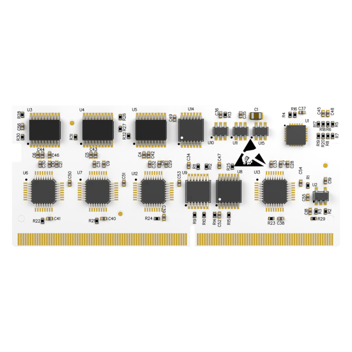
ESH10000590 is a precision analogue I/O module for Accordion systems with high-resolution analogue inputs and outputs for PCBA test, NPI and production test. It combines multi-channel ADC and DAC with per-channel calibration and flexible channel modes, controlled entirely in software through Accordion's channel and API model.
Specifications, connections & manual
All technical material on the page — expand a section, or download the whole datasheet as a PDF.
Specifications
| Parameter | Value | Notes |
|---|---|---|
| Function | Precision ADC / DAC module | |
| ADC channels | 12 | Single-ended, ADS124S08 |
| ADC resolution | 24-bit | |
| DAC channels | 8 | AD5675R |
| DAC resolution | 16-bit | |
| ADC communication | SPI | Internal bus |
| DAC communication | I²C | Internal bus, address 0x0C |
| Calibration | Gain + offset per channel | Persistent storage |
| Pseudo-digital mode | ADC + DAC | Configurable VL/VH |
| Numeric result acquisition | ADC only | Multi-sample, multi-channel |
| Max sample rate | Up to 4 kSPS per ADC | Data-rate dependent |
- ADC input range: −2.625 V to +2.625 V (bipolar) or 0 V to AVDD (unipolar), depending on configuration and supply.
- DAC output range: 0–2.5 V (gain = 1) or 0–5 V (gain = 2), referenced to the internal 2.5 V reference.
Manual
Channels
Channels follow {ModuleIndex}.ESH10000590.{ChannelName} — e.g. 0.ESH10000590.ADC05. User channels: ADC00–ADC11 (inputs), DAC00–DAC07 (outputs), CALIBRATION (table access). All channels must be explicitly enabled before use.
Modes
- Analogue — precision voltage input/output; configurable gain, offset, resolution; calibration gain/offset applied in hardware.
- Pseudo-digital — ADC and DAC channels via VL/VH thresholds (VH > VL; values between retain the previous state). In output mode the DAC drives VH or VL per logic state.
- Numeric result (ADC only) — high-speed/multi-sample, multi-channel synchronized capture, optional reduction (min, max, average, std-dev), base64 payload, referencing ADC channels via
TargetNetName.
Calibration
The CALIBRATION channel exposes the full table — read returns it as base64, write stores updated gain/offset. Data is persistent and applied on module reset.
Hardware
ADC: Texas Instruments ADS124S08 (SPI). DAC: Analog Devices AD5675R (I²C). GPIO expander PI4IOE5V6416 for internal routing. Low-level bus control is handled on-module and is not user-accessible.
Pinout
The module exposes 12 ADC channels (24-bit) and 8 DAC channels (16-bit):
| Channel range | Internal device | Description |
|---|---|---|
| ADC00–07 | ADS124S08 | ADC channels 0–7 |
| DAC00–07 | AD5675R | DAC channels 0–7 |
| ADC08–11 | ADS124S08 | ADC channels 8–11 |
Application notes, cases & news
Insights tagged for this product.
The right Accordion for your bench?
Tell us what you're testing and we'll find the right configuration — or say honestly if a standard setup is enough.