6x IDC N-TOP Breakout Module
96 DATA-bus signals broken out to six 20-pin IDC connectors — direct fixture access on top of the Accordion.
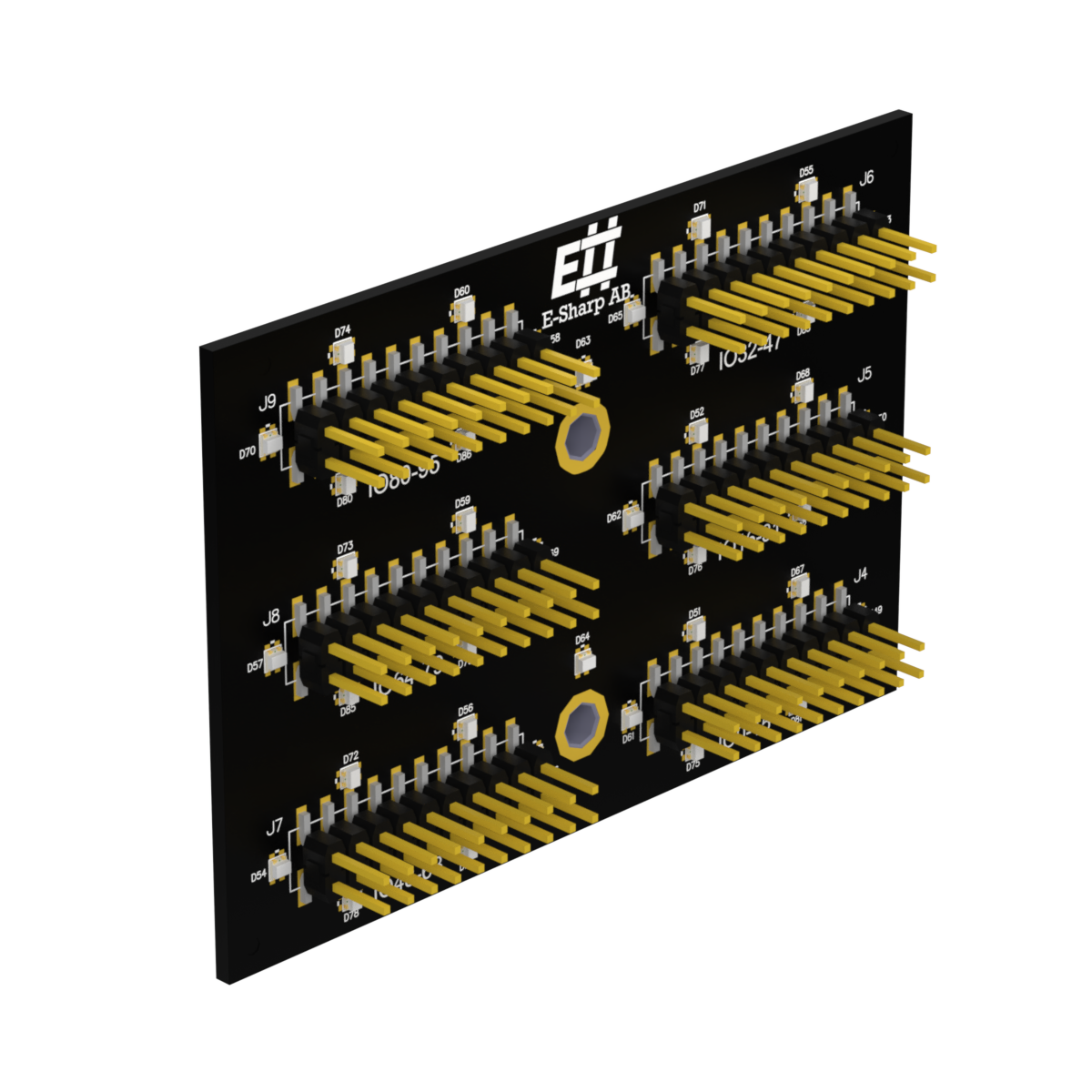
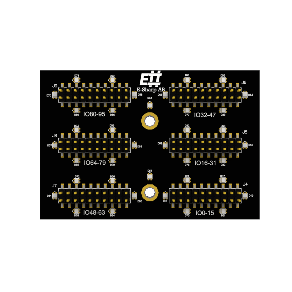
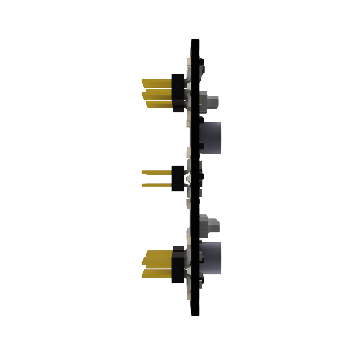
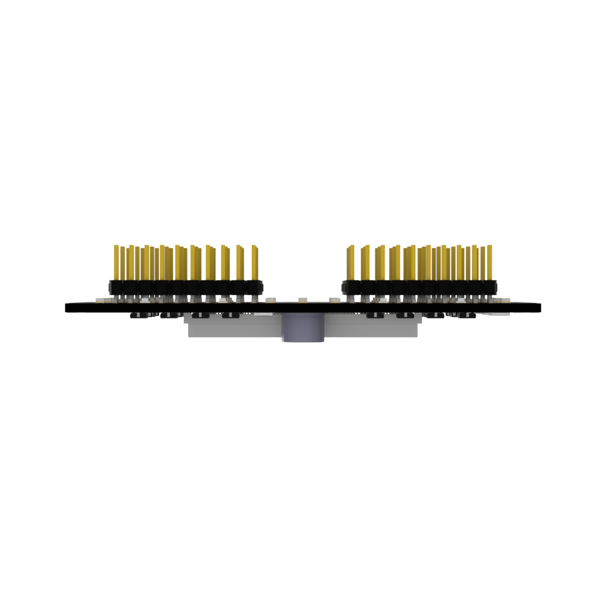
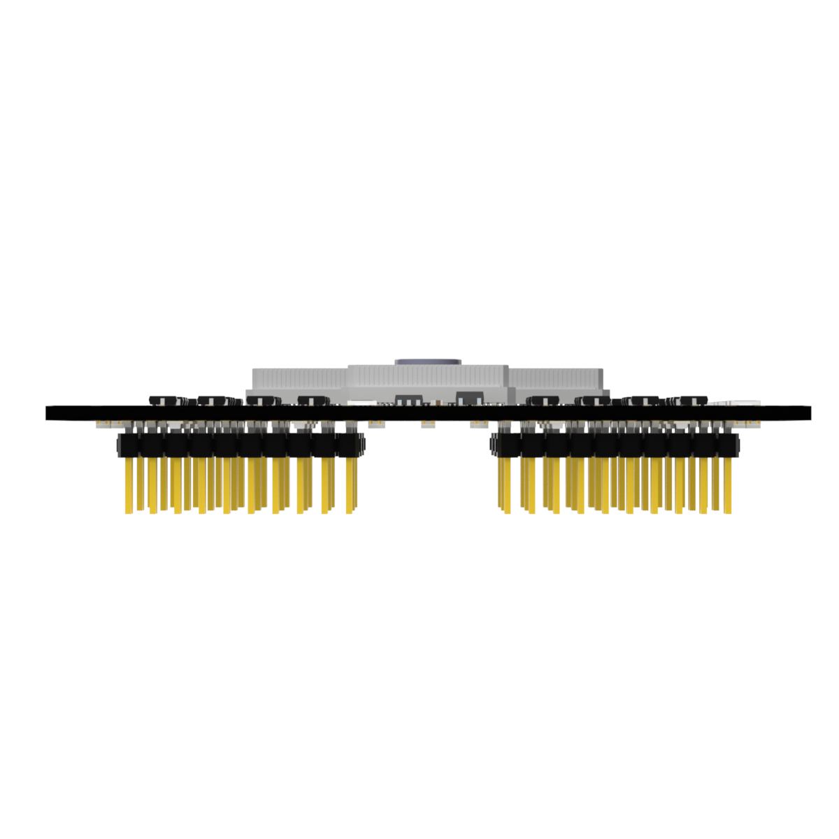
The 6x IDC N-TOP Breakout Module is an N-TOP module for the Accordion and Accordion A2 test systems that mounts on top of the chassis and exposes the full 96-line DATA bus on six standard 20-pin IDC connectors. The module is fully passive — signals route 1:1 from the system DATA bus to the IDC pins, with no active components and no signal conditioning in the path. It is the simplest way to get fixture cabling onto the Accordion DATA bus, and it lets you design your fixture around stock 20-pin ribbon cables.
At a glance
- Module type: N-TOP — mounts on top of the Accordion / Accordion A2
- User signals: 96 (DATA[0–95]) from the Accordion DATA bus
- Connectors: 6 × IDC 20-pin (2×10, 2.54 mm pitch), J1–J6
- Routing: 1:1, passive — no active components
- Per-pin max: 5 V, 2 A
- Auxiliary rails per connector: 5 V (pin 1) and 12–20 V (pin 2), each with a 0.25 A thermistor fuse
- ESD protection: IEC 61000-4-2, ±30 kV contact and air discharge
- Compatible systems: Accordion, Accordion A2
What it does
Each of the six IDC connectors exposes 16 DATA lines: J1 carries DATA[0–15], J2 carries DATA[16–31], and so on through J6 with DATA[80–95]. Pin 1 of every connector carries a fused 5 V rail, pin 2 carries a fused 12–20 V rail (both 0.25 A thermistor fuses), and the remaining pins are ground returns and DATA. That is enough to drive an LED, a small relay, or a level shifter directly off the ribbon cable, without dragging a separate supply into the fixture.
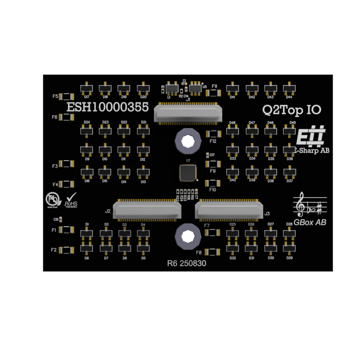
Because the module is passive, there is no driver, no firmware, and no calibration to manage. Channel access happens against whichever active module is sourcing the signal — an MPIO-96, a Precision ADC/DAC, or another DATA-bus module sitting in the corresponding bottom slot — addressed by its logical channel name through the standard Accordion API. The breakout is just wire, and that is the point.
The N-TOP slot the breakout is in determines which SO-DIMM on the top board it reads: N1 → T1, N2 → T2, N3 → T3, N4 → A1. The mapping is fixed, so the physical pin a given channel lands on is fully predictable from the slot assignment — useful when you are debugging a fixture or generating wiring diagrams from a channel map.
Trade-off to flag: this is a passive breakout. If the fixture needs signal conditioning, isolation, level shifting beyond what the auxiliary rails support, or active multiplexing, that work has to happen elsewhere — on the source module or in the fixture itself.
How it fits into Accordion
The breakout drops into any free N-TOP slot (N1–N4) on the Accordion or Accordion A2 top board. Insertion is keyed, so it only seats one way; like all N-TOP modules, swap with the system powered down. Once installed, the 96 DATA lines from the underlying SO-DIMM are presented directly on J1–J6 in a fixed, documented mapping. From there, standard 20-pin IDC ribbon cables connect the breakout to the test fixture.
Typical use
- Fixture cabling for PCBA test, NPI, and production test, using stock 20-pin IDC ribbon
- High-density digital and analog channel access in automated test systems
- Interface to custom or off-the-shelf test adapters that already speak 20-pin IDC
- Direct, predictable channel-to-pin mapping for fixture design and bring-up debug
Full specifications
Full electrical specifications, the N-TOP slot to SO-DIMM mapping, the per-connector pinout (including the fused power pins and ground returns), and worked routing examples for MPIO and Precision ADC/DAC modules are maintained in the E-Sharp Help Center. See the 6x IDC N-TOP Breakout Module reference.
Full electrical specifications, the N-TOP slot to SO-DIMM mapping, the per-connector pinout (including the fused power pins and ground returns), and worked routing examples for MPIO and Precision ADC/DAC modules are maintained in the E-Sharp Help Center. See the 6x IDC N-TOP Breakout Module reference.