The Accordion platform
Architecture, channel model, modules, software, and customer cases — the full story behind the Accordion test system.
List price
€4,595
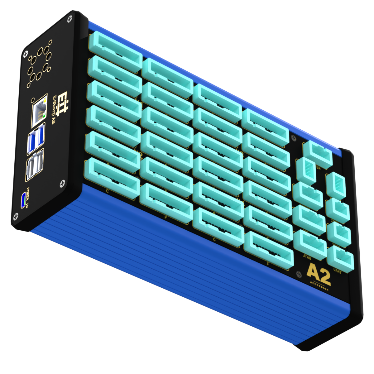
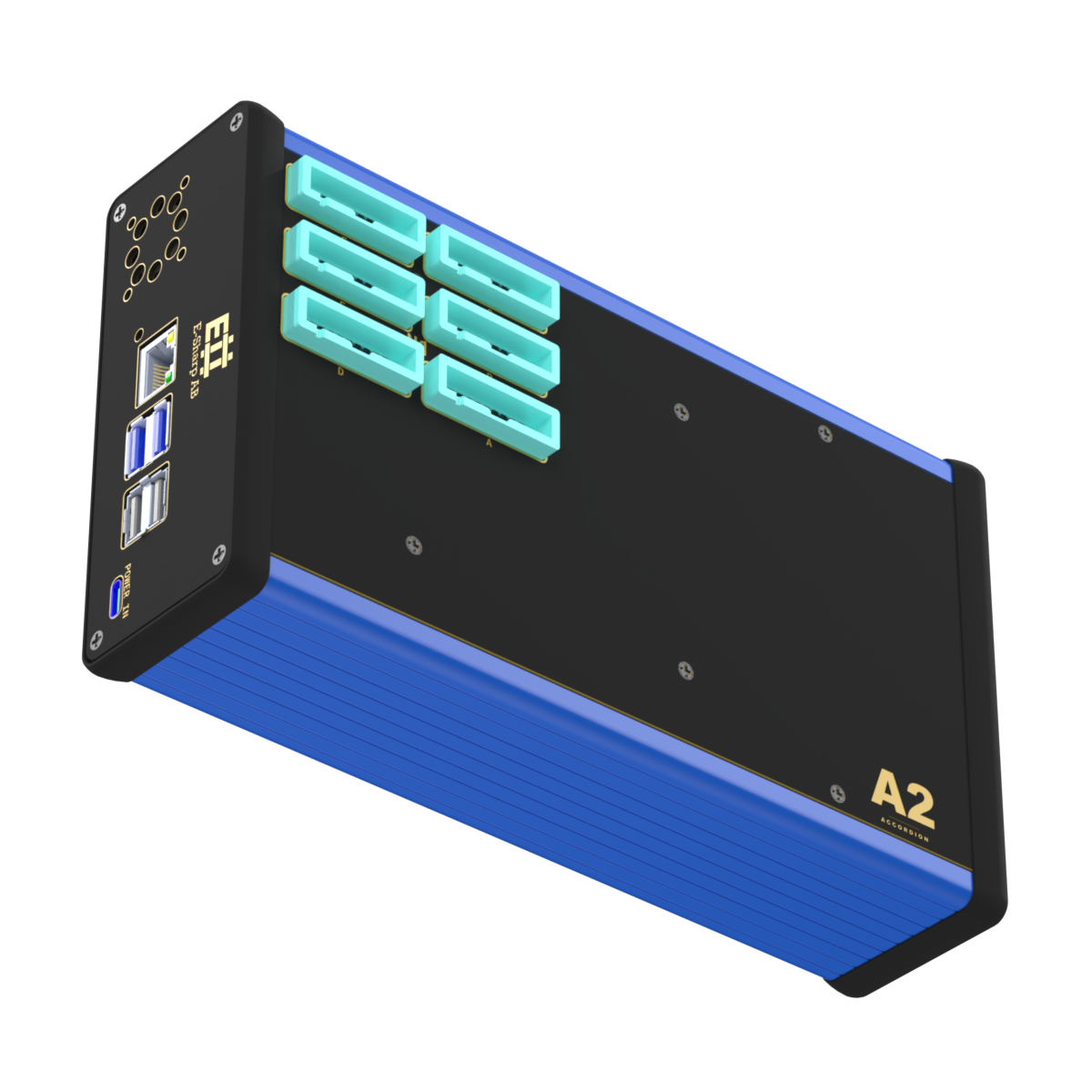
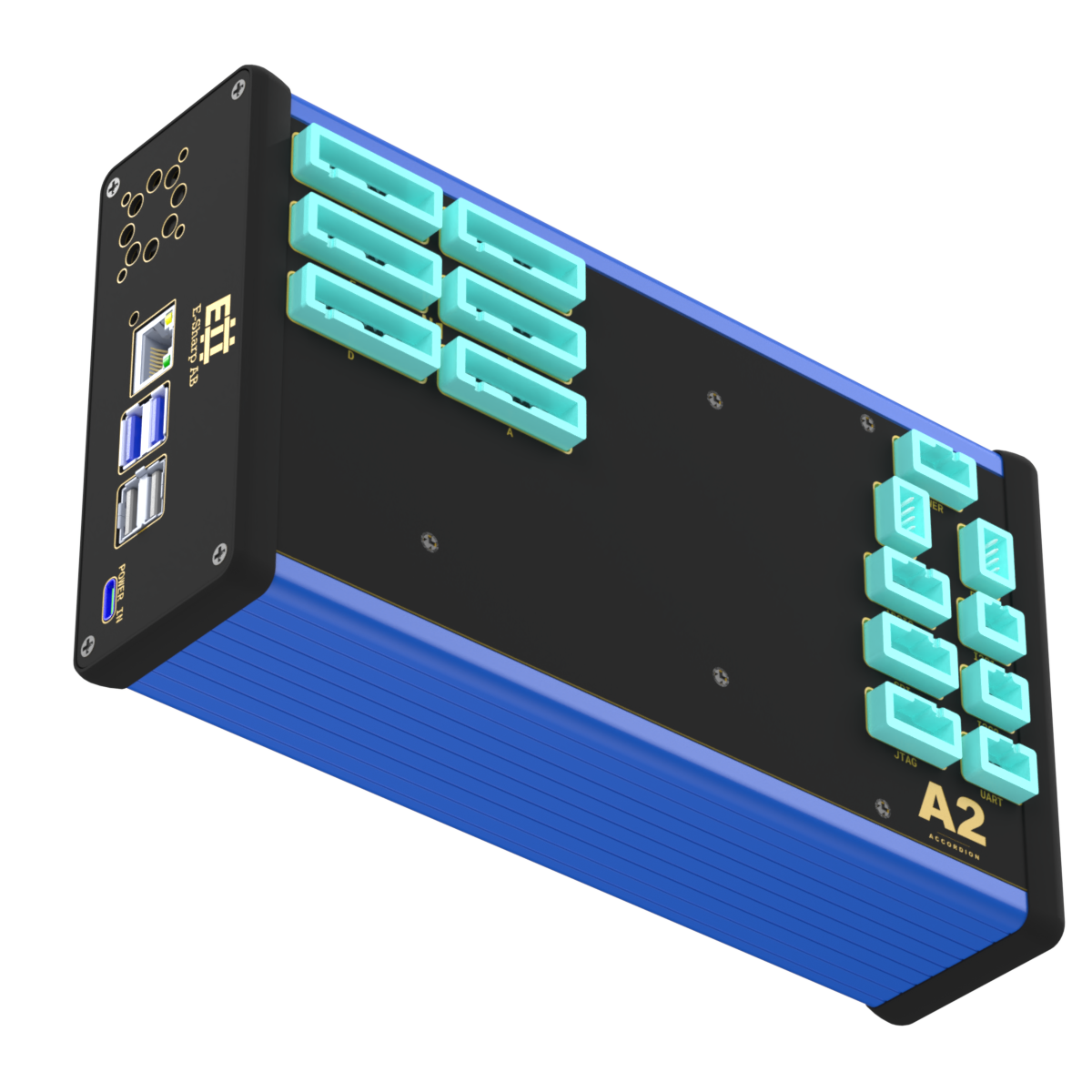
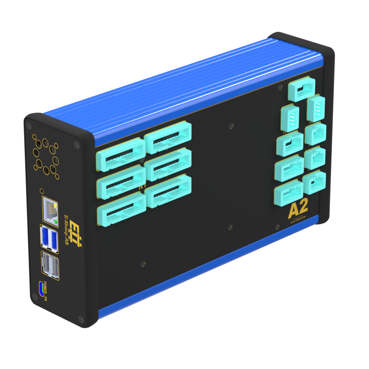
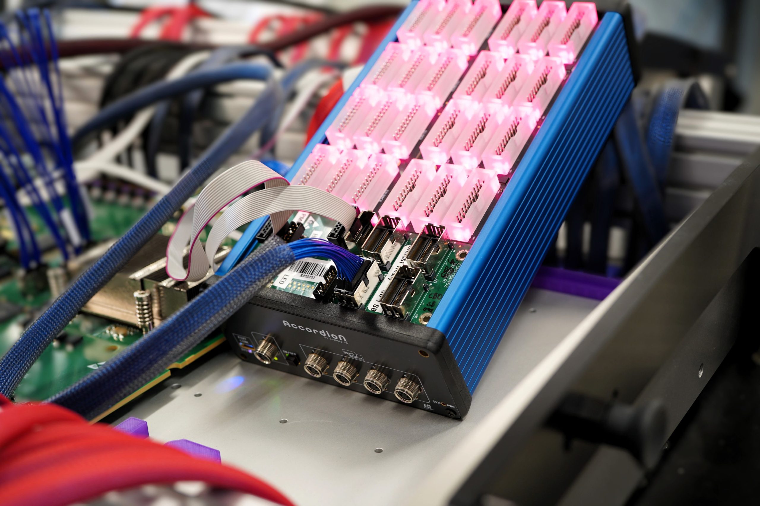
The Accordion A2 Plus is a fully-loaded configuration of the Accordion test platform — a single test node that powers, exercises, communicates with, and monitors a DUT without composing the configuration from individual modules. It ships with four pre-installed modules: the MPIO-96 SPI module (96 reconfigurable mixed-signal channels), the 6× IDC N-TOP breakout (fixture wiring), the M.2 PSU module (dual-channel programmable supply), and the Communication module (I²C, UART, SPI, JTAG, fan control, and RGB status indication). Lifetime Accordion Pilot and Accordion Shell licenses are included.
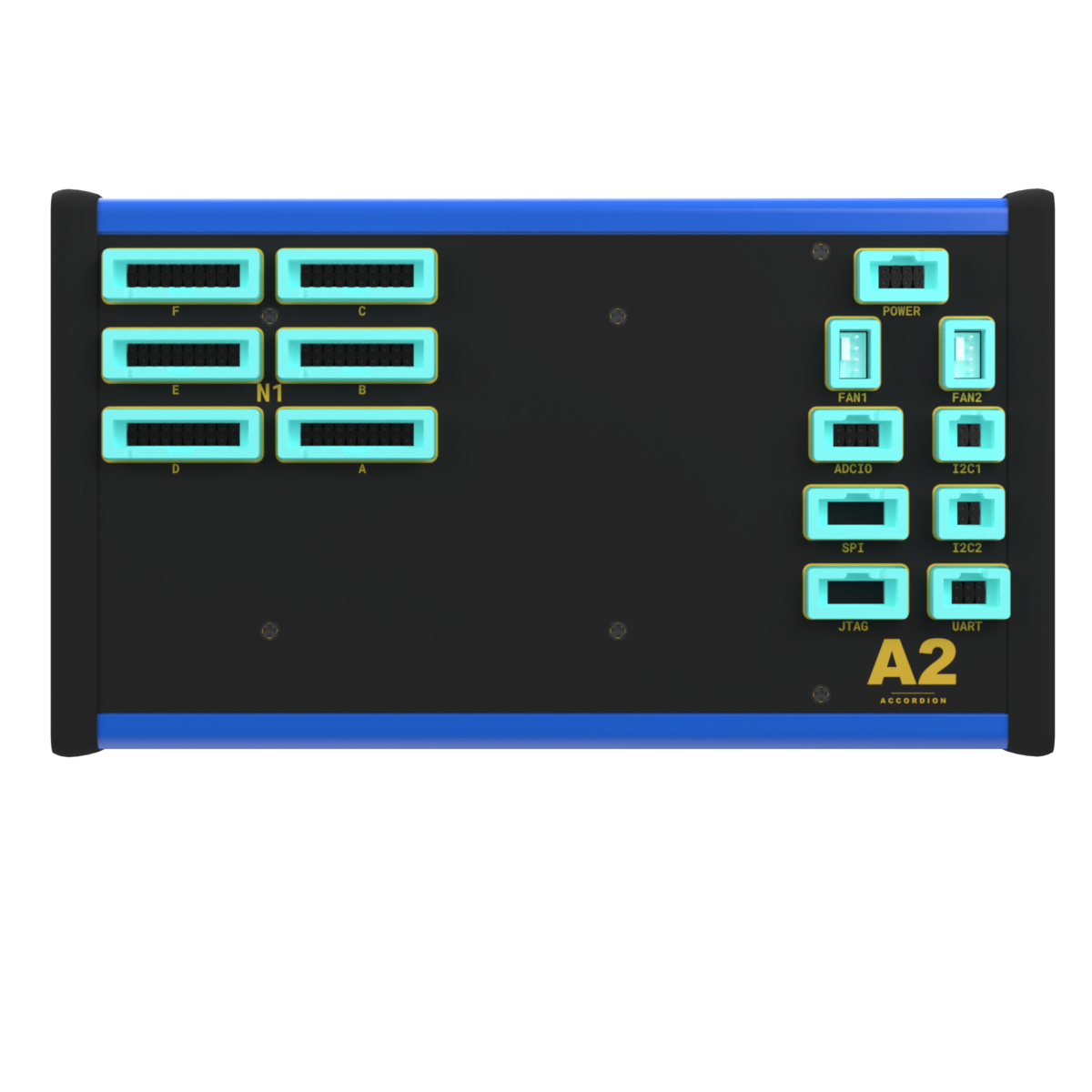
On the signal side, the A2 Plus presents 96 user channels via six standard 20-pin IDC connectors. Each channel can be reconfigured at runtime — analog input, analog output, or pseudo-digital with programmable VL/VH thresholds. Open-drain and floating-output behaviour are emulated by setting thresholds out of range, useful for external pull-ups and mixed-signal nodes. Resolution is bounded by the AD5592R devices on the MPIO-96: 12-bit ADC and DAC, 0–5 V typical in 2× mode.
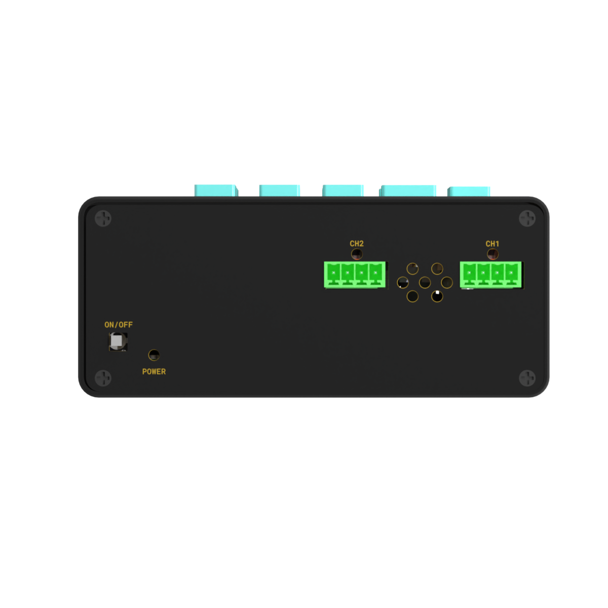
On the power side, two fully independent DC outputs are configured and read entirely in software via PMBus. Each channel covers 0–20 V and 0–10 A; the module enforces a 60 W combined ceiling and supports overvoltage, undervoltage, overcurrent, temperature, and startup-timing protection. Telemetry — output voltage, current, power, input voltage, input current, and temperature — is available per channel as discrete read-only registers. Outputs are disabled at boot and require explicit software enable.
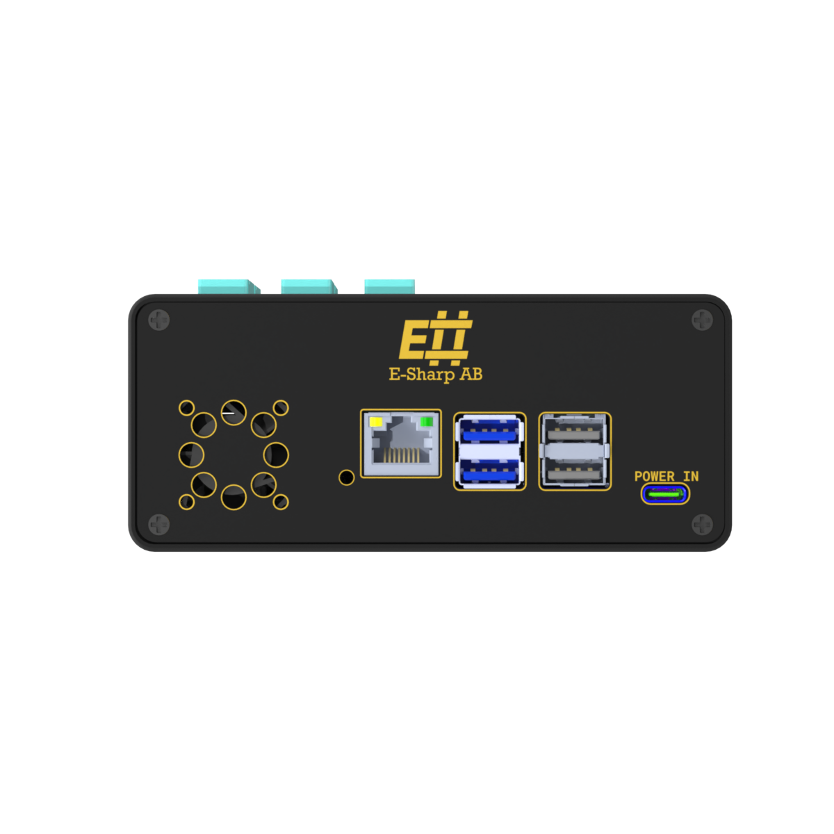
On the communication side, the A2 Plus exposes two software-controlled I²C buses (each with programmable rail and switchable pull-ups), an RS232 UART, SPI, and JTAG. SPI and JTAG share a single programmable rail and so cannot be powered at different voltages simultaneously — sequence them in software if both are needed. Two PWM fan headers with tachometer feedback and eight RGB status LEDs (mapped to bus, power, fan, and ADC/IO indicators) round out the operator-visible side.
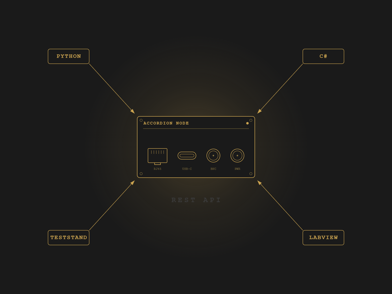
The A2 Plus is a fully fledged Accordion node. It is reachable on the network by hostname or IP, addressed by Accordion’s standard channel-naming convention, and controllable through the Accordion API — Python, C#, TestStand, LabVIEW, or REST. The Pilot and Shell licenses ship with the unit; the API clients are open and require no additional licensing.
The chassis still has free capacity for later expansion: three SO-DIMM slots, three N-TOP slots, and one M.2 slot are unpopulated. The Communication module sits on a dedicated communication position and does not consume an N-TOP slot.
The full datasheet — electrical specifications, channel-naming conventions, calibration procedures, IDC and module pin layouts, and integration examples for Python, C#, and TestStand — is maintained in the E-Sharp help center. See the Accordion A2 Plus help center page.
Specifications
The full datasheet — electrical specifications, channel-naming conventions, calibration procedures, IDC and module pin layouts, and integration examples for Python, C#, and TestStand — is maintained in the E-Sharp help center. See the Accordion A2 Plus help center page.
When the standard bundles don't fit — special connectors, additional modules, specific form factors — E-Sharp custom-builds the system.