Accordion Expand I2C Module
Connect Agent Expand units to Accordion Agent with long-range I2C and power distribution. Scalable, flexible, and engineered for growth.
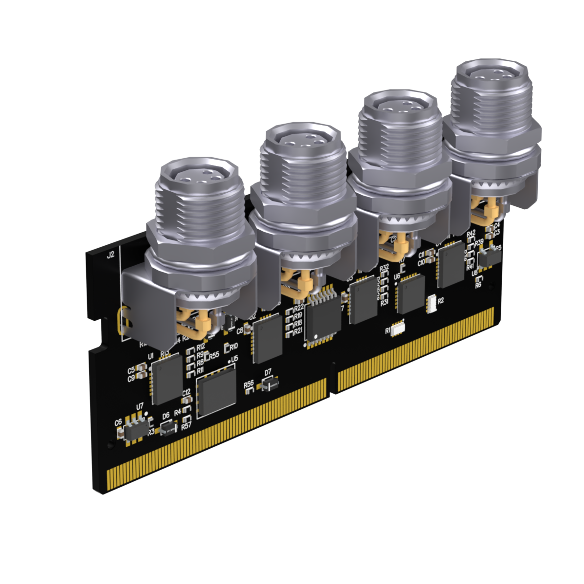
The Communication Module is the central coordination point between your host PC and every peripheral module in an Accordion test system. It exposes two I²C channels, UART, SPI, and JTAG with per-bus programmable voltages, controls fans and status LEDs, and acquires synchronized analogue data — all through one API. Installed as the top module of the stack, it is the piece that makes an Accordion behave as a single software-defined instrument.
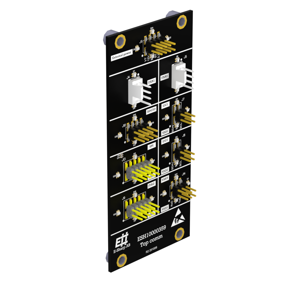
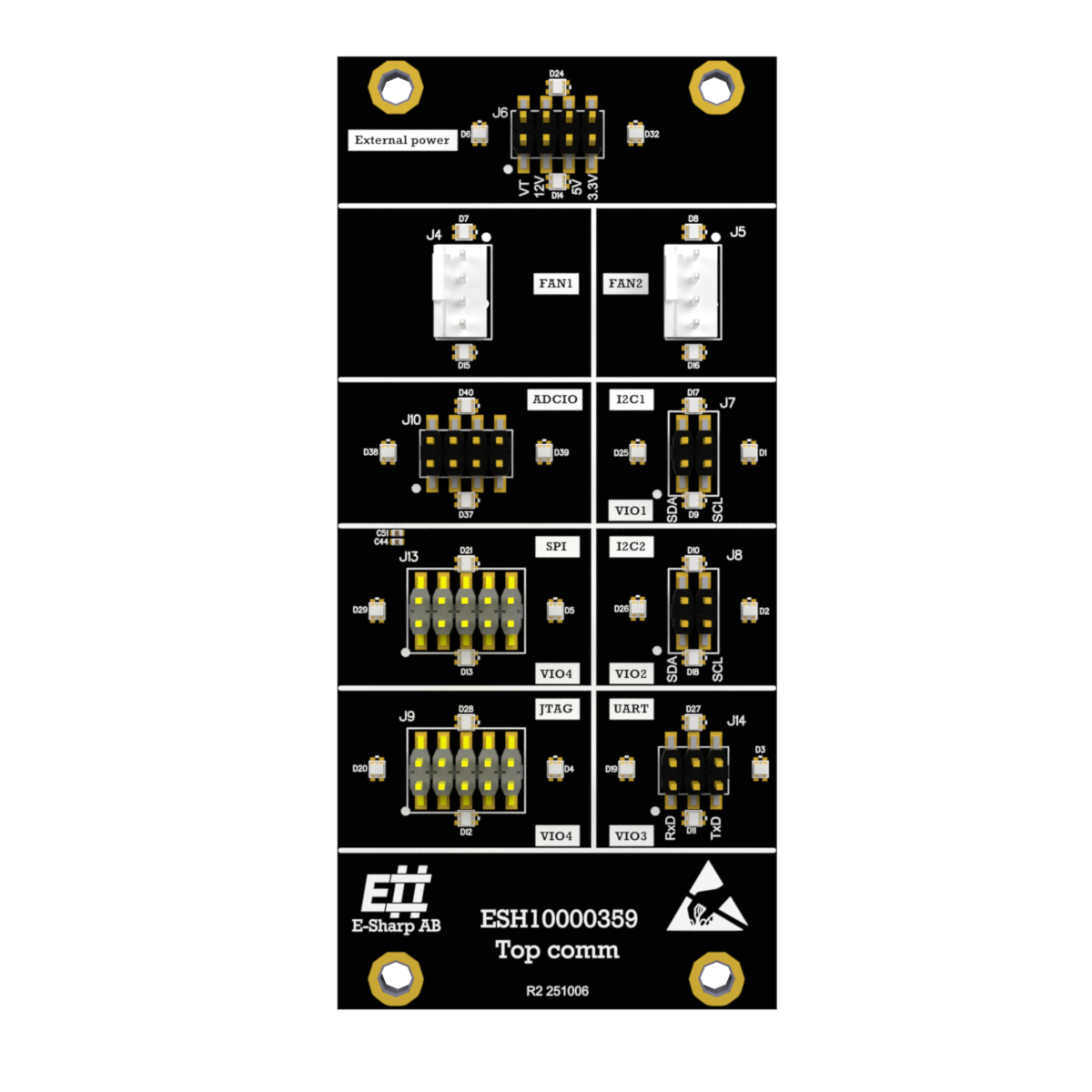
The module is, first, a protocol hub. Two I²C channels run independently with software-controlled enables, software-controlled 1 kΩ pull-ups to a programmable VI2C, and named channels you reference directly from a test step. UART (RS232), SPI, and JTAG sit alongside, each with their own programmable voltage rail. SPI and JTAG share a single rail (SPI_JTAG_VOUT) — a deliberate trade-off that keeps the connector compact and is the right choice for the vast majority of fixtures, but worth knowing if you need both buses at different DUT voltages at the same time.
Beyond the buses, the module handles the supporting infrastructure of a test fixture. Four 12-bit analogue outputs and four MPIO channels cover sensor stimulus, rail monitoring, leakage measurement, and pseudo-digital I/O with VL/VH thresholds. Two PWM fan controllers with tachometer feedback close the loop on thermal management. Eight named RGB LEDs (I2C1, I2C2, UART, SPI, JTAG, POWER, FAN, ADCIO) give the operator immediate visual feedback on the line — useful when something fails on a Friday afternoon and the test report is two scrolls away.
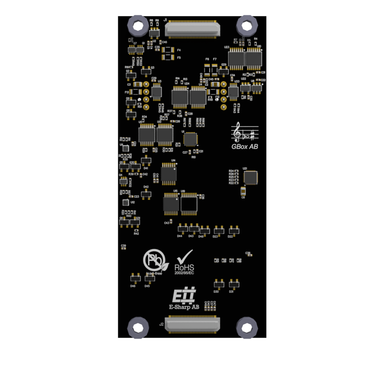
For high-speed work, the module performs synchronized multi-channel numeric acquisition and returns the result set as base64-encoded data. That is what makes leakage testing, rail-stability checks, and short sensor characterizations practical from the same module that is also driving the buses.
The Communication Module is the top module of an Accordion stack and uses ModuleIndex 15 by convention. Every channel follows the standard Accordion naming pattern 15.ESH10000359.<ChannelName> — for example 15.ESH10000359.I2C1_VOUT or 15.ESH10000359.SPI_EN. The recommended I²C startup sequence is consistent across both channels: set VOUT, enable the pull-ups, enable the channel, then transact.
Because every interface, voltage, and fan setting is software-defined, the same physical fixture can be reconfigured between products without rewiring. That is the point of Accordion, and the Communication Module is what makes it work in practice.
The complete electrical specifications, full connector pinouts (EXTPWR, FAN1/FAN2, I2C1/I2C2, ADCIO, SPI, JTAG, UART), named-channel reference, recommended I²C startup sequence, RGB LED conventions, protection thresholds, and C# and Python integration examples are documented in the E-Sharp help center: ESH10000359 — Communication Module.
The complete electrical specifications, full connector pinouts (EXTPWR, FAN1/FAN2, I2C1/I2C2, ADCIO, SPI, JTAG, UART), named-channel reference, recommended I²C startup sequence, RGB LED conventions, protection thresholds, and C# and Python integration examples are documented in the E-Sharp help center: ESH10000359 — Communication Module.