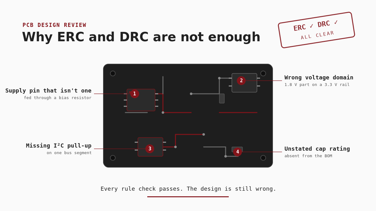
The I²C bus won’t enumerate. A channel is dead. An FPGA bank sits at the wrong voltage. You reopen the schematic and the layout, and everything matches what the tools reported: connected, spaced, rule-clean. The checks were never wrong. They simply answered a different question than the one that mattered.
This is the gap every hardware engineer meets eventually — the distance between a design that is legal and one that is right. Rule checkers verify the first. Nothing in the automated flow verifies the second. So it pays to know exactly where the line falls: what ERC and DRC genuinely guarantee, and what they structurally cannot. That knowledge is the difference between trusting a clean report and knowing when a clean report is only the start.
What ERC actually verifies
The Electrical Rule Check (ERC) works on the schematic and the netlist. Think of it as a consistency engine: it takes the connectivity you drew and the electrical properties on each pin, then hunts for combinations that break the tool’s electrical model.
In practice, a good ERC catches:
- Electrical conflicts — two outputs driving one net, an output tied to a power pin, an input that nothing drives.
- Connectivity faults — unconnected pins, single-pin nets, floating power inputs.
- Pin-type violations — a power input that never reaches a source, an open-collector output with no declared pull-up, bidirectional pins in an illegal arrangement.
ERC earns its keep, and skipping it is negligence. It clears an entire category of mechanical mistakes — the slipped wire, the forgotten connection, the dangling pin — before anyone spends attention on the design. A clean ERC therefore tells you the schematic is internally consistent: every net and every pin obeys the electrical rules the tool knows.
What ERC cannot know
Here is the catch. ERC verifies consistency with its own model, but it cannot verify that the model matches the circuit you meant to build.
Design intent lives nowhere in the netlist. The check knows a net connects pin A to pin B. It does not know you meant pin A to reach pin C. The legal net you drew simply goes to the wrong place. Both nets are valid. Only one is correct — and correctness is a fact about your intention.
Functional requirements sit outside its reach too. Nothing tells ERC that this rail should be 1.8 V, that this bus needs a specific pull-up to meet its rise-time budget, or that this reset must hold for a minimum duration. Those requirements live in your head and in the datasheets, not in pin properties.
System behaviour stays invisible as well. The check reasons about pins and nets in isolation. So it holds no model of power sequencing gone wrong, a bus master and a peripheral that disagree on voltage, or a control loop that looks stable yet runs marginal. Behaviour emerges from the whole system over time, and a static netlist check simply cannot see it.
In short, ERC confirms the schematic is a valid schematic. It says nothing about whether it’s your schematic — the one that does the job.
What DRC actually verifies
The Design Rule Check (DRC) works on the physical layout. Where ERC reasons about connectivity, DRC reasons about geometry: it compares copper, drills, spacings and the layer stack against a rule set — usually your fab’s capabilities plus your own constraints.
A well-configured DRC catches:
- Geometry violations — trace widths under the minimum, drills too small, thin annular rings, silkscreen over pads.
- Clearance failures — copper closer than the allowed spacing, thin creepage on a high-voltage section, acid traps and slivers.
- Manufacturing breaches — unsupported via types, sub-process feature sizes, solder-mask slivers, edge-clearance rules.
Like ERC, DRC earns its place. Because of it, boards come back built as drawn rather than as a pile of shorts and opens. A clean DRC against an accurate rule set means the layout is manufacturable: the fab can build it, and what they build matches your copper.
What DRC cannot know
Yet a clean DRC says nothing about whether the geometry implements the right circuit.
Take a pull-up to the wrong rail. A resistor from a signal to a 3.3 V plane and the same resistor to a 1.8 V plane look identical — two pads, a trace, correct clearances. DRC sees copper that obeys every spacing rule, and it has no concept that one plane is wrong for this bus.
Consider a part in the wrong voltage domain. Route a 1.8 V supply pin to the 3.3 V rail and the trace is still just a trace; it meets width and clearance rules. Nothing in the geometry encodes “this pin must not exceed 1.98 V,” so the check stays clean while the part over-stresses the moment power comes up.
Almost any faulty design decision behaves the same way, as long as it is physically well-formed. Think of a supply pin fed through a high-value resistor, a capacitor with no rating on file, an I²C segment that lost its pull-up, a differential pair routed to length but to the wrong pins. Each one produces rule-clean copper. What was wrong was the decision; its layout is flawless.
DRC answers “can this be built, and built as drawn?” That question matters. However, it is not the same as “should it have been drawn this way?”
Where ERC and DRC stop
Both checks are indispensable, and both ERC and DRC stop at the same line — the boundary between rules and intent. Set them side by side, and the pattern is hard to miss: each guarantees a form of correctness, and each is blind to the same thing.
| ERC | DRC | |
|---|---|---|
| Works on | Schematic / netlist | Physical layout |
| Guarantees | Electrical consistency — connections made, pin-type rules obeyed, no output conflicts | Manufacturable geometry — trace and drill sizes, clearances, DFM rules |
| Cannot know | Design intent · functional requirements · system behaviour | Whether the rail, value, and domain are the right ones |
| Passes anyway | A supply pin fed through a bias resistor; a part in the wrong voltage domain | An I²C segment with no pull-up; a capacitor with no rating on file |
Four real errors that pass ERC and DRC
The point turns concrete when you look at the mistakes engineers actually ship — every one of them through a clean ERC and DRC.
1. The supply pin that isn’t a supply
Two I²C repeaters on a recent board had their supply pin connected to the 3.3 V rail through a 200 kΩ resistor.
Everything about that is legal. ERC sees a supply pin connected to a power net — no undriven input, no output conflict, nothing to report. DRC sees a correctly sized trace to a correctly placed resistor. Both tools go green.
The part does not come up. 200 kΩ cannot deliver a device’s operating current, so the pin sits at a bias voltage rather than a supply voltage. The datasheet is explicit about what follows: the bus pins enter a high-impedance state whenever either supply falls below its under-voltage lockout threshold. Two channels are dead on a board that passed every automated check.
Catching it takes three facts held together. The datasheet says that pin is a supply, not a reference. In the BOM, the part is a 200 kΩ resistor, not a 0 Ω link. And the netlist shows no other path to the rail — the node has exactly four pins, one of them a 100 nF capacitor. Any one of those alone reads as ordinary. ERC holds the netlist and not the datasheet; DRC holds the geometry and neither.
The tell was on the same board, twice over: two more repeaters of the identical part, with their supply pins on a real rail. The design knew how to do it correctly. One corner of the schematic just didn’t.
2. The wrong voltage domain
A level-sensitive input on a 1.8 V device gets fed from a 3.3 V GPIO, because someone merged the two nets on the assumption they shared a domain. Electrically the connection is legal — an output drives an input — and the geometry is clean. But the part sits outside its absolute-maximum rating from first power-on, and the failure stays intermittent enough to survive bring-up and surface as field returns months later.
3. The I²C segment with no pull-up
A pull-up is one resistor. Finding the segment that lost one is not a one-resistor problem.
A management bus on a modern board is not a wire. It fans through a mux, crosses buffers, and splits at every series damping resistor into segments that look like separate nets and behave like one. On a board we reviewed recently, a single I²C domain resolved into sixty net segments across two masters, four repeaters and an eight-channel mux. Which of those sixty needs its own pull-up is not something you can see by scrolling the schematic.
It is also not something connectivity alone can answer. Some segments need no external pull-up at all. The repeater on them supplies an internal current source, and its datasheet says so — describing a part meant to allow the removal of external pull-up resistors on one side. Read the copper and that segment looks unpulled. Read the copper and the datasheet, and it is correct by design.
ERC does not classify a net as I²C, so it never asks the question. DRC sees legal copper either way. Answering it takes the netlist joined to per-pin device function. Which side of which repeater each pin is on, which rail each resistor reaches, which series element the review must look across.
Probe checks that join and reports the segments that come up short. Whether the resistor value then suits your bus length and loading is a sizing calculation. It stays where it belongs — with the engineer, now working from a correct segment map instead of a schematic scroll.
4. The capacitor whose rating nobody stated
Derating failures rarely look like a wrong number. They look like a missing one.
A ceramic rated 16 V on a 14 V rail with transients is a judgement call. A ceramic whose rating never made it into the BOM is not — it is a hole, and it reads exactly like a pass. Nothing in ERC or DRC has an opinion on a capacitor’s voltage rating, so a board can clear both with every rating on it unknown.
Probe joins each populated capacitor to the rail it actually sits on and to its rated voltage. Then it scopes the check to the caps where the rating carries risk. A part on a 0.85 V rail is covered by any standard ceramic and isn’t worth anyone’s attention. On the rails where it matters, an under-rated part is a finding, and an absent rating is also a finding: a stated gap with a named fix, not a silent pass.
That distinction is the whole point. A review that cannot tell “checked and fine” from “never checked” is not a review. On one board this surfaced eighty-eight risk-bearing capacitors with no rating on file — not eighty-eight defects, but eighty-eight places where a clean report would have been a lie.
Notice the common thread. The tools didn’t fail; each did exactly its job. Every one of these four turns on something the rule checks structurally cannot judge — design intent, device function, or a missing fact — rather than on legality. And none of those is something an automated checker can model. As one design-verification write-up puts it, a clean report quietly becomes a proxy for correctness, and that substitution is where the escapes hide.
See how Probe links findings to the design data behind them.
See ProbeThis is why design reviews exist
Every mature hardware team already knows the tools miss things, which is why the design review exists as its own step. Here, a human — ideally one who didn’t draw the board — asks the question no checker can: does this design do what we intended?
A review is different work
A review is not a rule check performed by a person; it is a different kind of work. The reviewer rebuilds intent from the schematic and the datasheets. They check the real values and connections against what the design should do. And they reason about behaviour the static checks miss — sequencing, margins, domain crossings, corner cases. That is why experienced engineers say a genuine review costs effort comparable to doing the design itself. It isn’t a formality bolted on at the end; rather, it’s the verification step that covers everything the automated flow cannot.
And it’s the weakest step in practice
Unfortunately, this is also the step that tends to be weakest. Often the reviewer can’t even open the design without a CAD seat. One vendor’s own community forum admits that “consuming one license just for the review is not economical.” So reviews happen over exported PDFs and screenshots in a spreadsheet, far from the real data. Meanwhile, the findings that do surface land in an email thread or a chat message, then vanish by the next project. And the reviewers themselves stay scarce: often one or two senior people for a whole team, increasingly close to retirement, so when they leave, the review knowledge leaves with them. In other words, the step meant to catch what the rules miss is the step most likely to be rushed, undocumented, or skipped.
What a good design review needs
If the review — not ERC and DRC — is where correctness actually gets verified, it’s worth being precise about what makes one effective — beyond the checklist every designer already keeps. Four things matter most.
Access to the design
The reviewer has to open the real board — nets, components, and the functions they belong to. A static export won’t do. A viewer that shows shapes without connectivity is close to useless; the forum lament that “the error was not in the CAD tool… but actually in the Gerber viewer” captures why. And access can’t depend on a CAD seat, or most of the people who should review never will.
Traceable findings
A finding has to attach to the thing it concerns — this net, this component — and persist. When findings live in email and Slack, they get lost between projects and stay invisible to an auditor. Traceability isn’t bureaucracy. Instead, it lets a finding survive long enough to act on, and long enough to find again.
Evidence
A finding backed by proof is a different object from an opinion. “I think this pull-up is wrong” invites debate. “This pull-up goes to the 1.8 V rail, and this device needs it on 3.3 V — here’s the datasheet page” ends it. Evidence turns a review from a contest of seniority into a matter of record. It also lets the engineer who fixes the issue verify it in seconds instead of re-deriving it.
Knowledge retention
A finding is worth more than the meeting it was raised in. Today most of them evaporate — a comment in a thread, gone by the next project. When a finding stays attached to the part and the net it concerns, it carries forward instead. The next board that uses the same component starts from what the last review already learned — not from zero.
Get those four right, and the review stops being the weakest link. Miss any of them, and the blind spot stays uncovered — no matter how disciplined the rule checks are.
How Probe approaches the problem
This is the problem E-Sharp built Probe to work on — not to replace ERC and DRC (run them; they do their job) but to give the human review the four things above.
Probe reviews the design you already have, at whichever stage you are at. Before layout, it works from the schematic and the BOM alone, so a review can start at the front of a project. After layout, it ingests the ODB++ you already export for fabrication, joined with that schematic and BOM. Either way, anyone can open the design without a CAD license: follow a net through connectors and series parts, see the function a component belongs to, search the whole board.
A review finding attaches to the net or component it concerns and carries its proof — the netlist line, the layout location, the datasheet value. Because that evidence is structured rather than buried in a thread, a finding raised once carries forward: the next board that uses the same part inherits what the last review learned. And where teams run an AI assistant, Probe holds it to the same standard as any reviewer. It queries the actual board over MCP and cites the exact data behind every answer — and where the data can’t support a claim, it says so rather than guessing from general knowledge.
None of this decides whether the design is good — that call still belongs to the engineer. What it does is hand the person making that call a design they can open, findings they can verify, and a record that outlives the meeting. ERC and DRC tell you the board is legal; this is the layer that helps a human confirm it’s right.
Probe doesn’t simulate — and that’s the point of it
Probe won’t draw you a timing diagram or a Bode plot. Those come from SPICE, and they answer a different question. Simulation tells you how a circuit behaves once it’s already wired the way you think. That needs a model for every part and a testbench to drive it. On a board of any real size that testbench doesn’t exist. So simulation happens on slices — a supply loop, one critical link — run by a specialist, late, and rarely.
Review sits one level up. Before you can ask how the board behaves, you have to know it’s the board you meant to draw. Every part has to be used inside its rules. Is this pin a supply and not a reference? Is this capacitor rated for its rail? Does this net have one driver, not two, with no floating input? Those are the errors that most often kill a first article. Simulation never reaches them — you could never build the bench to see them. Answer them first. A clean simulation of the wrong netlist is just a confident wrong answer.
Probe reviews the whole board for that kind of correctness, with no simulation to set up. Three questions decide whether a board works. Is it legal and manufacturable? That’s ERC and DRC. Is it the design you meant, used within its limits? That’s review. And given both, how does it behave? That’s simulation. This article has been about the middle one — the one nothing else on the bench is asking.
ERC and DRC are the beginning, not the end
ERC and DRC are not the problem, and this isn’t an argument against them. They are the foundation: a design that hasn’t passed them isn’t ready for review at all. The mistake is treating a clean report as the finish line. It certifies one thing — that the board is a valid, manufacturable version of the netlist you drew — and nothing more. Whether that netlist is the one you meant to draw is the question the tools can’t reach, and it’s the question that decides whether the first article works.
That question has always belonged to the design review. ERC and DRC made the mechanical errors cheap to catch. What remains are the errors of intent — and those still need a human, with the design in front of them, the evidence in hand, and a record the next board can learn from.
Probe is in development, launching later in 2026. If the errors that slip past your rule checks are the ones that keep costing you spins, register your interest and we’ll tell you the moment it’s available — no obligation. Or bring a design and book a 30-minute session: we’ll load your schematic, BOM and ODB++ (or just schematic and BOM if you’re pre-layout) and run a live review together.